


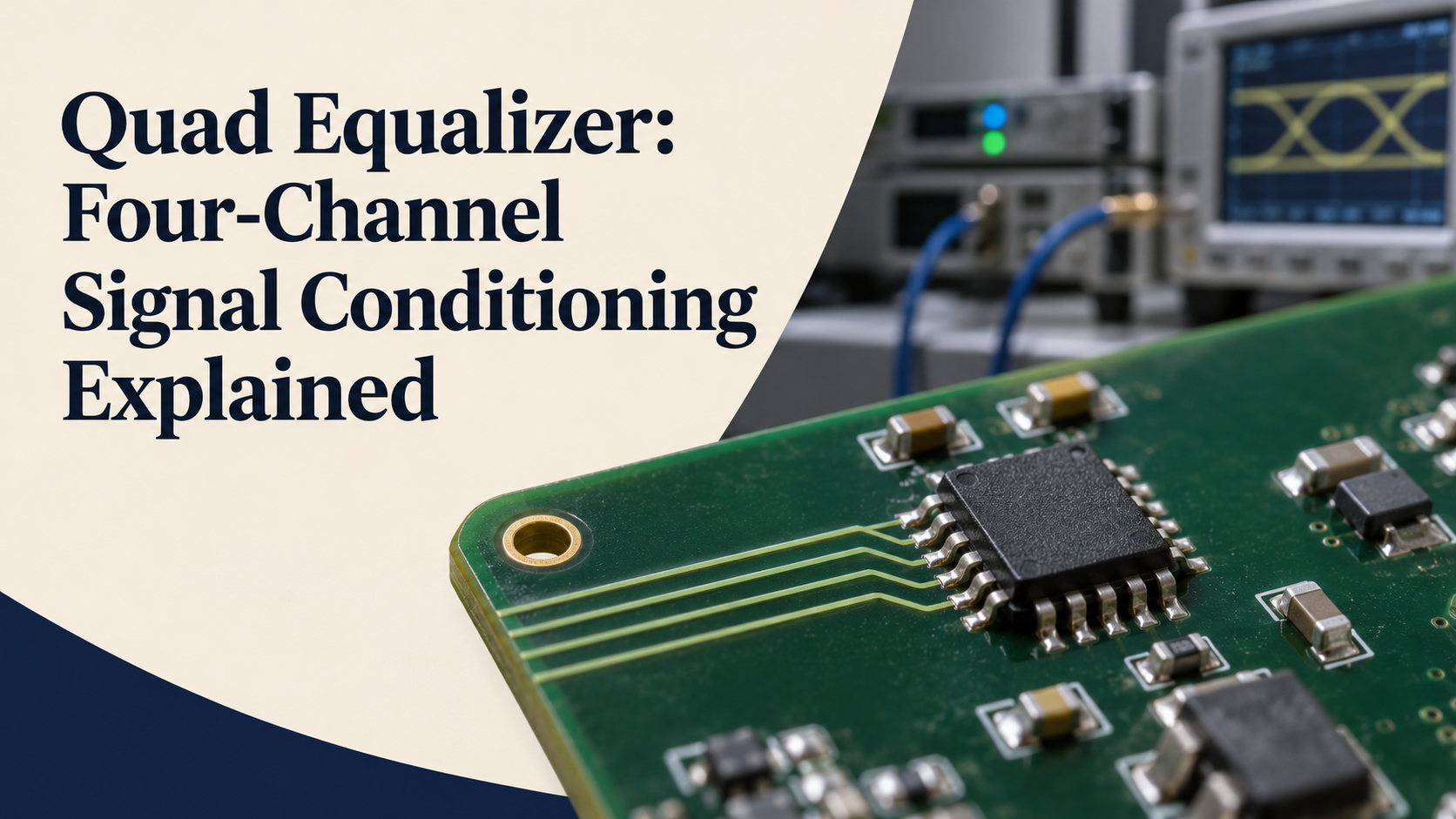
A quad equalizer, in high-speed electronics, is a device that provides equalization for four data channels. It helps compensate for signal degradation through a circuit-board trace or cable, but the phrase does not identify one universal chip or guarantee compatibility with every interface.
The first useful step is to identify the actual part number. Texas Instruments uses the term for the DS32EV400 DisplayPort device, while Analog Devices describes the MAX14950 as a quad PCI Express equalizer/redriver. Those examples perform related signal-conditioning work in different design contexts, and they should not be treated as interchangeable components.
What Quad Equalizer Means
“Quad” refers to four channels in the manufacturer examples discussed here. “Equalizer” describes circuitry that compensates for aspects of transmission loss, helping the receiving end distinguish the changing data signal. The word is being used in a data-interface context, not as a claim about a consumer music equalizer.
The Texas Instruments DS32EV400 product page identifies four channels and lists a maximum operating speed of 3.2 Gbps. It also describes programmable equalization and individual channel controls. These are specifications of that particular device, rather than definitions that apply to every product carrying the category name.
A channel count alone does not tell you how an entire connection is arranged. Read the device’s block diagram and the interface requirements together. Signal direction, channel mapping and support circuitry need to match the intended application, not simply the number four in the description.
Why High-Speed Links Need Conditioning
Sending data through a physical interconnect changes the electrical signal. Board materials, connectors and cables all contribute to the channel that lies between transmitter and receiver. At high data rates, a design needs enough signal margin for the receiver to interpret transitions reliably.
Texas Instruments’ explanation of redrivers and retimers describes equalization as a way of compensating for an attenuated signal. It is a signal-integrity function, not a method for changing the content being transmitted or increasing a protocol’s advertised generation.
A device added to a link must therefore be selected for a known problem. Establish whether the design is limited by channel loss, jitter, a routing problem or another issue. Adding a component without understanding the limitation can make the board more complicated without addressing the cause.
Equalizer, Redriver and Retimer Are Different Terms
An equalizer changes the signal response to compensate for channel characteristics. A redriver provides signal conditioning and drives the signal onward. A retimer goes further by recovering timing and retransmitting the data through its own timing process.
The PCI-SIG comparison of retimers and redrivers explains the distinction in the PCI Express context. The choice affects what a designer can expect the component to correct. A redriver should not be credited with all the capabilities of a retimer merely because both are described as signal conditioners.
The terminology on a specific datasheet takes priority over a generic buying description. Some products combine equalization with other functions, and two chips with similar marketing names may use different architectures. Check the functional description before comparing headline speeds.
Two Manufacturer Examples
The DS32EV400 is a DisplayPort-oriented quad equalizer. TI lists eight programmable equalization levels and control through pins or an SMBus interface. Its published supply and package details belong to that design and need to be checked directly before any implementation.
The Analog Devices MAX14950 is described as a quad PCI Express equalizer/redriver, with programmable input equalization and redrive functions. Its product information identifies support for particular PCIe generations. That does not make it a drop-in replacement for the DisplayPort example.
These examples show why the part number matters more than the category label. A buyer should also distinguish the base product from similarly named variants. A letter added to a model number can represent a different device, package or channel arrangement, so check the exact orderable part and its own documentation.
Read the Datasheet Around the Actual Application
Begin with the supported protocol, signalling rate, number of channels and intended topology. Then check the electrical requirements, including supplies, coupling, input and output characteristics, temperature range and control method. The design must meet all relevant requirements together.
Absolute maximum ratings are not operating targets. Likewise, a typical figure should not be treated as a guaranteed limit under every temperature and process condition. A careful comparison uses the applicable minimum, maximum and test conditions rather than collecting the most attractive number from each page.
Check revisions as well. TI’s linked DS32EV400 datasheet and Analog Devices’ MAX14950 documentation provide detailed information beyond their overview pages. Keep the document revision with the project records so later reviews can identify which requirements were used.
Programmable Boost Needs Measurement
Programmable equalization gives a designer options for matching the device to the channel. It does not imply that the highest available setting is always best. The useful setting depends on the loss being compensated and on the behaviour of the complete link.
Plan how those settings will be selected, recorded and tested. A configuration that works on one development board may not be the correct choice after a connector, cable or routing length changes. Where the product allows channel-specific settings, consider whether the channels actually have the same electrical path.
Evaluation should cover the conditions the finished product will encounter. A clean result in one short bench test is a starting point, not proof that every production unit will meet the interface requirements. Use appropriate signal-integrity methods and the relevant compliance process for the design.
Layout and Evaluation Hardware
The board is part of the signal path, so layout cannot be treated as an afterthought. Consult the manufacturer’s routing, power and grounding guidance and examine the package requirements before finalising component placement. The objective is to preserve the intended signal path around the conditioner, not just to connect matching pin names.
Analog Devices provides a MAX14950 evaluation kit as a reference for evaluating the device. An evaluation board can help investigate configuration and behaviour, but its success does not certify a different board layout or a different cable assembly.
Record the complete setup when comparing results: board revision, component variant, settings, cable, endpoints and test conditions. That makes a later failure easier to reproduce. Without those details, apparently contradictory results may simply come from different systems.
Common Selection Mistakes
One mistake is choosing by data rate alone. A number that appears high enough does not establish protocol compatibility, electrical compatibility or the required control behaviour. Another is assuming every four-channel device has the same internal signal direction or package connections.
A third mistake is treating an older part as a general solution for a newer interface generation. Compare the actual supported standards and the manufacturer’s current documentation. A continuing product listing does not mean the component is intended for every modern application.
Finally, do not confuse a component-level specification with a guarantee for the finished product. The transmitter, receiver, interconnect, layout and configuration still form one system. The equalizer is a tool within that design process, rather than a substitute for it.
Frequently Asked Questions
Does quad mean four channels?
Yes, in the manufacturer examples covered here. Confirm the channel arrangement and direction in the particular datasheet rather than inferring a complete link topology from the word alone.
Is a quad equalizer an audio device?
The products discussed here condition high-speed digital data. Audio equalization uses related terminology in a different context, so a search result needs to be matched to the intended application.
Can it turn an older link into a newer protocol?
No such general claim follows from equalization. The component, endpoints and interconnect must support the intended interface requirements; signal conditioning does not redefine the protocol.
Should equalization always be set to maximum?
No. Select and validate settings for the actual channel using the manufacturer’s guidance and suitable measurements. More compensation is not a universal improvement.
Are DS32EV400 and MAX14950 interchangeable?
No. They are documented for different interface contexts and have their own electrical, packaging and control requirements. Compare exact part numbers and datasheets before selecting a device.
